Productive Nanosystems From molecules to superproducts


This page is about the the conceptual animation video "Productive nanosystems: From molecules to superproducts".
Watch it here: Productive nanosystems: From molecules to superproducts (InternetArchive link)
To address the common immediate concerns see: Macroscale style machinery at the nanoscale
Other proposals for gem-gum factory designs that differ from what is shown in the here discussed video can be found on the page: "Discussion of proposed nanofactory designs".
(wiki-TODO: add screen captures to the detailed discussions)
Contents
[hide]- 1 Goals
- 2 Brief listings
- 3 More in depth discussion
- 3.1 List of shown things in the first half (zoom-in)
- 3.2 List of shown stations (zoom-out)
- 3.2.1 Sorting rotors
- 3.2.2 Final transfer into machine phase
- 3.2.3 Tooltip loading, Tooltip preparation, Carbon deposition (Tooltip unloading)
- 3.2.4 Assembly line positioning stage
- 3.2.5 Omitted non-shown details
- 3.2.6 Routing station
- 3.2.7 Mixed part type stream transport to the next assembly level (here next assembly layer)
- 3.2.8 Stream pickup mechanism (crystolecule presenter)
- 3.2.9 First programmable assembly robot
- 3.2.10 NOT SHOWN second lockout and speed-change
- 3.2.11 Part streaming assembly
- 3.2.12 Final lockout at the macroscale
- 4 Notes
- 5 Related
- 6 External links
Goals
Suspected goals of the concept animation video
The goals of this animation presumably where a balance of:
- accurate depiction of concepts outlined in the book "Nanosystems" and tooltip chemistry papers
- comprehensible depiction of concepts
(not over designed over complicated – just giving a hint that there are plenty ways to do it) - keeping design effort manageable
- show the most critical components worked out in most detail =>
less critical components are worked out in much less detail
they are mostly shown to give a whole system context
Goals of this discussion page
This page is about
- a brief listing of the sequence of things shown in the video followed by
- a bit more detailed in context discussion of the processing stations will then be given in dedicated subsections. Eventually illustrated with corresponding screen captures.
Discussion of processing stations that get to long will be factored out into dedicated pages that will discuss these ideas mostly outside the context of this concept animation video.
Brief listings
List of shown things in the first half (zoom-in)
Shown wile zooming in continuously:
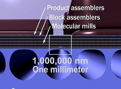
- Macroscale resource cartridges
- Cooling channels
- Assembly layers
Shown while zooming out is a list of processing stations.
List of shown stations (zoom-out)
Stations dealing with molecules and molecule fragments:
- Sorting rotors – specifically here: Acetylene sorting pump – Nanosystems pages 374, 378, 379
- Final transfer into machine phase – this may split up into sub processes – Related:Machine phase
- Tooltip loading
- Tooltip preparation
- Carbon deposition – specifically here: di-carbon deposition – Tooltip unloading
Stations dealing with crystolecules and bigger structures:
- Assembly line positioning stage – pallets (adapter pallets)
- NOT SHOWN IN PUBLISHED VERSION – attachment chains for the tool-tips and back-pressure rails
- NOT SHOWN – Tooltip positioning stage
- NOT SHOWN – switch of attachment chain type
- NOT SHOWN – chain speed transition
- NOT SHOWN – early stage vacuum lockout
- Routing station (Distribution junction and merging junction)
- Mixed part type stream transport to the next assembly level (here next assembly layer)
- Stream pickup mechanism
- First programmable assembly robot – details largely omitted
- NOT SHOWN – second vacuum lockout – eventual second speed change
- Part streaming assembly – this splits up into three sub processes – gantry robotics involved
- Final lockout at the macroscale
More in depth discussion
List of shown things in the first half (zoom-in)
The continuous zoom-in is nice. Attempting to give a sense for scale.
For even better ways to do this see:
Macroscale resource cartridges
Yes, could be done that way, yes, but a power-bank form-factor might be more convenient.
(Or a plug to the global microcomponent redistribution system.)
Also the lab setting is kinda funny.
One major point of this technology is that people would have these devices in their living-rooms or working-rooms (like photocopiers)
and in their backpacks like laptops.
See: Form factor of gem-gum factories
Cooling channels
Not much to say here I guess.
Could and would be implemented by more advanced means then just passive tubes for cooling fluid.
See: diamondoid heat pipe and diamondoid heat pump
That (not being limited by viscosity) could and would integrate more into the assembly layers above.
Nothing of that is shown though.
Just as energy and data systems are not shown at all.
Assembly layers
Maybe this is interpreting to much into how much thought went into this concept animation but
The thickest layer being the one with the smallest nanomachinery and further up layers with bigger nanomachinery getting thinner matches up perfectly with
"deliberate slowdown at the lowest assembly level" something we probably want to implement to keep waste heat from friction in check and
something we should be able to implement mainly thanks to "higher productivity of smaller machinery".
List of shown stations (zoom-out)
(wiki-TODO: add discussions of stations and associated screencaps)
Sorting rotors

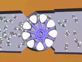
"Sorting rotors" is the name used in Nanosystems.
Possible critique points of what's shown in the animation:
Possible critique (1): "This has not been worked out in enough detail." – (not applicable when looking at additional work)
Well. Given this is a processing step of core importance there actually has been done more detailed work on this peculiar design problem.
The results juts did not make it into the animation. Either for reasons-of-clarity or it may have been designed only after publication of that video.
Specifically an atomistic model of an acetylene sorting pump with the software Nanoengineer-1 was being designed.
See: Acetylene sorting pump – This was the biggest and most complex modeled diamondoid molecular machine element designed till 2021 (and going).
Possible critique (2): Potential critique points due to the integrated polyine rods:
- possibly higher radiation damage sensitivity.
- the component parts are possibly quite a bit more difficult to synthesize
Are there maybe alternative solutions that can do without polyine rods?
See discussion on the page: resource molecule sorting system
Final transfer into machine phase

This is not shown in a way that is well worked out at all.
A system quite similar system to the sorting rotors (like acetylene pumps) might be the intention here.
An issue here might be that
- on the fluid/gas phase side temperature must be high to prevent freezing.
- on the machine phase side temperature may need to be cryogenic to prevent the not yet covalently bond molecules to come loose and poison the practically perfect vacuum.
If that indeed is an issue then a thermal difference may motivate stetching out that mast wheel to a chain over a macroscopic distances though a thermal isolation barrier. This wold be a quite different design approach. For the preceding resource molecule sorting system similar alternate approaches might make sense too.
Tooltip loading, Tooltip preparation, Carbon deposition (Tooltip unloading)
Here basically some results of these paper are presented:
- A Minimal Toolset for Positional Diamond Mechanosynthesis (paper)
- (wiki-TODO: add reference to paper about the DC10c tooltip)
- The featured tool for di-carbon deposition is likely DC10c.
- (wiki-TODO: find out which tool was demonstrated doing the hydrogen abstraction)
See also:
Assembly line positioning stage
See main article: Assembly line positioning stage
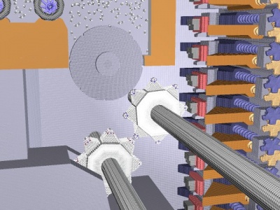
This is a positioning stage that is attached to each attachment chain link of the crystolecule mechamosynthesis assembly line. These stages allows for individual x,y,z positioning in a quite ingenious and minimalistic way.
This design is exploiting the peculiar physics of the nanoscale quite a bit. A lot of stuff is held together only by the Van der Waals force. The very same design at the macroscale would just fall apart to (thousands/millions/whatever) pieces (except all pieces where strongly magnetic in convenient directions – impractical)
This is a case where there is quite a bit of deviation of macroscale style machinery at the nanoscale. But few notice. In fact the positioning stages themselves can be easily miss one's attention since they are not explicitly mentioned in the animation videos narrative.
Omitted non-shown details
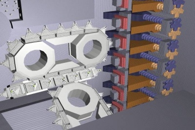
Attachment chains for the tool-tips and back-pressure rails:
A version that did not make it into the final video had these.
See second screen capture.
Tooltip positioning stage:
Designing rotational degrees of freedom causes some head-scratching.
Plus the preceding point was ditched. That may be the reason for why it is not shown.
(TODO: have a go at designing positioning stages for rotational degrees of freedom)
Switch of attachment chain type:
There is a switch from one attachment chain type to another attachment chain type.
From the one with assembly line positioning stages to a plain one.
This is not narrated and easily missed.
There must be a mechanism doing that transfer.
Change of attachment chain speed:
Given this wikis assumption of deliberate slowdown at the lowest assembly level is correct,
then going up the assembly levels we need to speed up (in terms of distance per time not in terms of frequency).
This speedup step could be ...
- ... combined with the preceding chain type switching step.
- ... done separately.
- ... combined with the later routing step. – But it is done so here in the later shown routing design. It does not change speed.
Early stage vacuum lockout: A pretty critical omission. The bigger the volume the harder it gets to maintain a good PPV vacuum. One could argue that seamless covalent welding is still not done so a lockout this early is pointless. Later in the video there is no second stage vacuum lockout (after seamless covalent welding) shown either though. Only macroscale vacuum lockout is shown at the very end of the video. Possibly a good design idea was missing at the time of creation. The perfectly sealing two piston vacuum lockout design design presented on this wiki may be an original. See: vacuum lockout.
Routing station
This super-crude conceptual sketch is glaring too wasteful with space.
Although "there is plenty of room at the bottom" (as Richard Feynman said), this is a chip like context.
A real design would want to design things compcatly and cramp things together.
Furthermore gemstone nanoscale superelasticity is (braggingly) visually featured in the pickup mechanism (but not mentioned in the narrative).
Making use only of Van der Waals force (as doen in the positioning stage) would probably be sufficient (and smaller).
Given the speeds here might still be quite a bit under of the speeds that would result from scale natural frequencies, it might be acceptable to have quite small turn radii.
Slamming parts without slowdown into walls at much higher speeds would cause energy dissipation by thermalization into phonons.
(TODO: Have a go at desingning a somewhat more realistic smaller routing station)
Although this seems like one single mechanism it can be conceptually separated in pick-up and place-down.
Distribution-junction and merging-junction respectively.
This is a good place to add redundancy into the system (Nanosystems page 420 Figure 14.7.).
It's not mentioned in the videos narrative.
Mixed part type stream transport to the next assembly level (here next assembly layer)
This might go for quite a stretch given it needs to get out of the thick stack of the bottommost assembly level.
This being a long stretch is not shown in the video.
Splitup from many streams to one is also not shown.
Stream pickup mechanism (crystolecule presenter)
This really simple one degree of freedom mechanism is probably here in order
for the larger scale assembly mechanism to not to need to match up
its motion to the motion of the continuously running attachment chain.
Why does it not pick the parts via the (red colored) adapter palettes??
This means more one-off adapter designs. Something we really don't want.
- shown adapter palette design would require part turnaround
- shown adapter palette design does not allow for part handover
(TODO: Have a go on a better adapter palette design)
First programmable assembly robot
There are many many ways to do it. So all the details where entirely omitted.
Just look at the wild variety of RepRap 3D printers out there to get the variety.
High stiffness parralel type robotics are to prefer at this size scale though.
There is the same questin as before though: Why does it not pick the parts via the (red colored) adapter palettes??
NOT SHOWN second lockout and speed-change
Here after covalent welding is (mostly?) done may be the ideal place for perfectly sealing a vacuum lockout step.
Also another speed change may be in order.
Part streaming assembly
The shown design might help
- in overhangs
- different assembyl speeds at different locations ??
- ??
The shown process splits up into three sub processes
- streaming part presenter mill wheel
- length extendable transport chain
- final gantry robotics placement mechanisms
The conceptual polygonal wheels are likely a bad idea
due to Van der Waals force need in to rip off for every turn of a facet.
Final lockout at the macroscale
As mentioned before: There should be lockout steps before this late in the game.
Even worse there is no airlock shown. A macroscale perfectly sealing PPV airlock sounds challenging to say the least.
Without airlock every time the gem-gum factory is opened up it would fully flood with air (and dust/dirt) all the way into the tiniest nanoscale nooks and crannies. That would be a nightmare to get out again. Pumpout doen to to PPV vacuum (and even to in comparison crude UHV vacuum) is not a matter of just pumping at the top. That is due to free molecular flow behaving like a ballistic billard. Air molecules only hitting the walls not other gas molecules.
Notes
The page on this wiki that is associated is: Gemstone metamaterial on chip factories
The page "Advanced productive nanosystems" is more generally about all kinds of proposed advanced manufacturing systems (more and less feasible) that go into the direction of gem-gum technology.
Related
- Block diagram of a gem-gum on-chip factory
- Subsystems of gem-gum factories
- Assembly subsystem – Related: Routing levels
- Discussion of other proposed nanofactory designs
- Gemstone metamaterial on chip factories
- Design of gem-gum on-chip factories
- Tracing trajectories of component in machine phase
- Advanced productive nanosystems – Disambiguation page
- More generally: Advanced productive nanosystems
External links
- Watch it here: Productive nanosystems: From molecules to superproducts (InternetArchive link)
- (wiki-TODO: Add a link to a version with English and German soft-subs, such that it can be played w.o. sound.)
