Assembly levels
The assembly levels describe how an advanced productive nanosystem of technology level III will be organized. They constitute a greatly implementation agnostic scheme for the organisation of an advanced productive nanosystem on the bottommost levels. Assembly levels can be e.g. concretely mapped into a layered Nanofactory design or a partially fractal design.
Since waste is a serious danger of this potentially clean technology a special focus on recycling is taken here.
Note:
- Do not confuse convergent assembly with exponential assembly.
- A concrete implementation of all the assembly levels but IV is visible in the official productive nanosystems video [1]. The absolutely necessary airlock step is not shown.
- The here used terms in italic are newly proposed.
- Assembly levels aid in advanced nanofactory design
Contents
- 1 A Listing of Levels
- 2 Related topics
- 3 Related
- 4 External links
A Listing of Levels
Take-in and preprocessing (Level -1 and 0)
At the very first two processing steps there is no real constructive assembly yet.
And the manipulated structures do not yet grow in size.
Thus calling these processing steps "assembly levels" is stretching it a bit.
To still integrate them into the scheme of assembly levels
a good option might be to just give them numbers smaller than one like so:
- Processing step (PS=1) == Assembly Level (AL=-1)
- Processing step (PS=2) == Assembly Level (AL=0)
This way the "first assembly level" (Level I) is the first real "assembly level".
Take-in (PS=1, AL=-1)
What is happening here is a filtering/cleaning of resource material.
A lot of liquid phase (and maybe gas phase) processing is involved.
- Contaminants are removed
- resource molecules are (at the end of the process permanently) transferred from liquid phase into machine phase
- The entropy in the resource material is reduced
See: Purification mills
Preprocessing (PS=2, AL=0) (prepatation of tooltips)
Tooltip preparation / tooltip regeneration.
From here on out everything happens in machine phase.
From here on out everything: atom, molecule, and all bigger building-components are always and ever held onto.
Nothing is ever let go off. See: Never unclasp.
Here the tool-tips are:
- loaded up with feed-stock molecules (moieties),
- then sent up to the first real assembly level (AL=1)
- then return empty to be reloaded again.
A closed cycle like this is a lot more complicated than this simple description might suggests.
A lot of theoretical work has been done for a closed cycle for the mechanosynthesis of diamond and closely related pure carbon structures.
See here: A minimal Toolset.
For further information visit the pages about
First assembly level – Level I: (crystolecule synthetization)
- This is the third processing step (PS=3).
- This is the first real assembly level (AL=1) where small parts are getting put together to much bigger parts.
Summarized characteristics of this assembly level:
- In goes: fully preprocessed moieties on reusable tools
- Out goes: assembled crystolecules
- Processing is done in robotic mechanosyntesis cores in specialized assembly lines.
- The processing performed is force applying mechanosynthesis
About this assembly levels product – the crystolecules
The assembled crystolecules encompass:
- diamondoid molecular structural elements
- the parts that constitute diamondoid molecular machine elements
Crystolecules are most useful when they are designed to be reusable standard models.
For any kind of conceivable nano-system holds:
From every type (or set of types) of DMEs an enormous number of identical copies is needed.
(The reasons for this are nontrivial and lie in data-compression.)
Therefore for an efficient system
lots of specialized building chambers in
lots of specialized assembly lines for the different crystolecules makes sense.
This naturally leads to the on-chip nanfactory design.
Examples for a sets of standard parts (producible by specialized assembly lines) are e.g.:
Lack of reversibility on the first assembly level
A note on recycling: Mechanosynthesis is not necessarily (that is most likely in some processing steps not) reversible.
If diamond is used as building material then the carbon atoms that get bound as diamond (or similar) into the products
can only be brought back to the biosphere by burning of the crystolecules. (See: Diamondoid waste incineration.)
There are other diamondoid materials that are slightly water soluble and
may allow for an unattended route back to the biosphere.
Second assembly level – Level II: (sinterface welding & crystolecule assembly)
Here level I Diamondoid Molecular Elements (DMEs: DMMEs & DMSEs) are assembled to bigger non disassemblabel microcomponents. They are built in an evacuated building chamber thus their size is limited. They are assembled covalently by pressing compatible sinterfaces together and structurally by pick and place (think of putting rings on rods). To counter the thermal shaking effect (let go of a piece and it josts away instantly) which is prevalent in this size range parts which are supposed to move in the final product are held down by either VdW forces or sparsly distributed covalent bonds (predetermined breaking points) or a second gripper.
Finished microcomponents ready for assembly level III are complex or simple conglomerates of many small DMEs. The step from assembly level II to III is the soonest point where product parts can be expulsed to a non vacuum environment. Expulsion requires that all non enclosed unterminated radicals that should remain in the final product must be sealed. The consequent ban of irreversible surface interfaces makes the creation of monolithic non-modular non-reusable structures harder. (Finished microcomponents must only use interlocking or weak VdW sticking for interconnectivity.) Microcomponent expulsion sets a clear line preventing inter-mixture between assembly level II and III. For certain products (e.g. diamond single crystals) it would be necessary to defer product expulsion to higher assembly levels. Metamaterials from passivated microcomponents should be capable of fulfilling almost all our needs though.
Enclosed radicals may be used for locking mechanisms, springs, energy- and data-storage.
Recycling: In this assembly level surface interfaces of DMSEs are "welded" together. This step in most cases is irreversible. For recycling of the whole finished microcomponents it is highly advisable to keep all the outer interlocking mechanisms reversible and to physically tag all microcomponents so that they remain recomposable later-on even after they where shuffled. Open documentation will also improve chances for reuse and thereby help to minimize biosphere pollution.
Since at this level only whole DME blocks are handled most overhangs should be "printable" with only three degrees of freedom.
It makes sense to create for each product DME an adaper DME such that only one maipulater can grip a multitude of DMEs. High programmability is desired perhaps even more so than in the next assembly step where a lot of in place production can occur.
Reversibility on the second assembly level – Level II-R: (crystolecule component tweaking)
Finished level II microcomponents might provide some adjustability (on the DME size level) and or means for functional mechanical testing. General purpose maintainance units (level II & III) which remain in the final product should be able to operate these functions. And repair/replace/remove them based on the results.
Third assembly level – Level III: (component composing)
Here out of microcomponents finished in level II structures of arbitrary scale are built. Connections are made via interlocking possibly in an ambiet pressure envirounment. Dirt like chain molecules viruses and dust must be considered. Positional accuracy may be lower than atomic. The connectors restore atomic resolution by guidance.
Recycling: Note that there is a tradeoff between functional-density and module-reusability. The smaller the units get the more fundamental and reusable they will be, but they'll have much interlocking surface eating up quite a lot of otherwise usable volume.
Reversibility on the third assembly level – Level III-R: (component recomposing)
General purpouse maintainance units can recompose components to completely different makroproducts. Compared to "rezzing" products from level 0 this produces considerably less heat and can be done considerably faster. Hopefully a global network of machine phase component redistribution pipes will emerge at some not too late point in time.
Fourth assembly level – Level IV
An optional step. Some layers of convergent assembly can be added fro various reasons. One can think of convergent assambly as putting microcomponents together from the leaves to the root of an octree.
Todo: Find out the advantages of convergent assembly over direct assembly. (It's not speed.) They are mentioned but not really explained here: [2] Exponential assembly is more sensitive to disturbing vibrations / accelerations than direct assembly. Proucts are more anisotropic. A lot of quick macroscopic handling (makro scale reconfigurations) may be automated in a convergent assembly nanofactory capable of dealing with dirt from recycling. Interfaces / surfaces capable of self alignment and bonding from crude alignment by hand (quasi welding) would allow the topmost convergent assembly stages huge fault tolerances.
Recycling: A level IIIb and IIb system may be included into the product that bypasses Level IV so that products can execute self repair actions while running. (hot plugging)
Related topics
Interleaved component router systems and stocks
For the transport of unfinished product parts of different sizes from lower to higher assembly levels nanofactories may use routing structures.
The routing structures can either have separate or merged multiplexing and de-multiplexing steps where the former provides redundancy of rails. (Nanosystems Fig 14.7.)
There are two in some respects similar yet in other respects very different steps where this can occur.
- when diamondoid molecular elements (DMEs) are transported from assembly level I to II
- when microcomponents are transported from assembly level II to III
For all the optional steps in convergent assembly (assembly level IV) the lower stages should be programmable/steerable enough that no further shuffling is required. (Depending on the programmability the lower stages may too be simplified.)
Since direct control of the bottommost systems could clog the IO bottleneck hirachical heterogenous nanomechanical computing system must be integrated in parallel (one layer might suffice). Temporary storage facilities for microcomponents are optional (they may also be useful as seperate macroscopic entities).
[Todo: explain free space designs, analyze parallelism]
Product expulsion
In any technology level III productive nanosystem that uses vacuum up to the topmost assembly level (blending assembly levels, allowing for unrecyclable macroscopic maximum performance single crystals) a macroscopic perfectly tight lockout mechanism is necessary.
Vacuum lockout in the micro-scale at the soonest possible point in the convergent assembly process like described here may be easier and may enforce recyclability of products at the price that one needs to deal with dirt not just in product usage but already at the assembly time.
In E.Drexlers new book "Radical Abuncance" [add ref] the outlined system differs to the presented assembly levels in that it keeps the process in vacuum/noble-gas till the product is completely finished. This design avoids the complexity of dealing with dirt but introduces the complicity of providing appropriate vacuum at all convergent assembly levels (level IV). Note that for recycling one has to deal with dirt at least on the products surface in any way. An "isolation till finished macro-product" approach would further allow intermixing for Level II & III and thus allow for undissasemblable unrecyclable macro-products like one big diamond crystal. Such products may only be of interest for products that not just ought to work but are supposed to push the limits like in motor sports and in military interests. Well designed form closure connectors can retain almost the full material strength and may suffice for aerospace applications.
Recycling
A very important issue whenever responsibly designing nanomachinery is to aim for best waste avoidance. It does not come for free. The history of plastics show the dangers pretty well. But with APM systems one can take a range of countermeasures starting in their inherent design and buildng up with additional functions. Very desirable would be some kind of global microcomponent redistribution system parallel to our current water gas and electricity supply that couples to assembly level IIb.
Relation to product structure
Somewhat complementary to the assembly levels is hirachical product structure. A given product description (e.g. implicit volume definition) can be reversely subdivided into assembly level assembly steps and the assembly levels can be used as a guide for foreward product design (which is most prominent with microcomponents). [TODO: link Nanosystems]
Related
- Convergent assembly
- In place assembly
- More general including the in between levels (not necessarily layers): Chain of zones
External links
- Motivations for splitup into assembly levels (Level1 & Level2) can be found in Considerations for Self-replicating Manufacturing Systems by J. Storrs Hall, PhD. Institute for Molecular Manufacturing [3] [4]
Table of assembly levels
| How products are put together | ||||
|---|---|---|---|---|
| Building block | Assembly step | |||
|
|
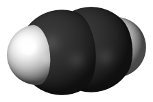
Level 0a: (~size<1nm) capturing sorting and purifying resource molecules from gas phase water or organic solution | |||
|
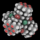
Level 0b: (~size~1nm) from captured raw material Molecules (above) to Moieties on tooltips (left) | |||
|
Level I: (~size<32nm) from Moieties on tooltips (above) to crystolecules (left) | |||
|
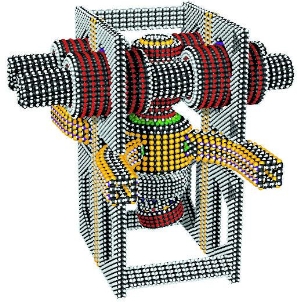
Level IIa: (~size~32nm) from crystolecules (above) to more or less monolithic parts (left) | |||
[todo: add other examples]
|
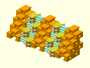
Level IIa: (~size~<1µm) from more or less monolithic parts (above) to recomposable µ-components (left) | |||
|
|
Level III: (~size~<32µm) from recomposable µ-components above to µ-component assemblies (left) | |||
|
|
Level III or higher: (~size>32µm) from µ-component assemblies (above) to diamondoid metamaterials (left) |
|||
|
|
Level III or higher: (~size>>32µm) from metamaterials (above) to yet alien products (left) | |||
